Industrial machines often need to transfer power between shafts that meet at an angle. A Bevel Gear set can make that change in direction within a compact space. You may find one in a vehicle differential, a packaging line, or a machine tool. The gears’ conical shape and tooth design help determine how smoothly they mesh and how much load they can carry. The details matter. Shaft angle, gear ratio, speed, torque, and operating conditions all affect the choice.
For engineers and maintenance teams, selecting bevel gears is not simply a matter of matching dimensions. Tooth contact, lubrication, housing stiffness, and alignment influence noise, heat, and service life. A small alignment error can leave uneven marks across the teeth, while inadequate lubrication may accelerate wear. Installation deserves attention. Straight, spiral, and other bevel gear designs suit different needs, and no type is best for every application. That point can be easy to overlook.
This guide explores why industries choose bevel gears, where they perform well, and what to check before specifying them. It also considers practical trade-offs, including cost, maintenance access, and operating noise. Actual results depend on the full drive system, not the gear alone. Good design helps, but careful inspection still matters.
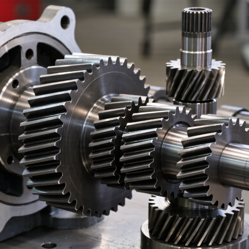
Bevel gears redirect power between shafts that meet at an angle, often at 90 degrees. Their cone-shaped teeth mesh across the shaft junction, allowing a motor’s rotation to drive a crosswise shaft. That turn matters. It can help fit a drive into a narrow machine frame, such as a compact conveyor or mixer. The gear ratio can also change speed and torque, depending on the selected tooth counts. A right-angle layout may look simple on paper; bearing stiffness and assembly tolerances make it less simple in practice.
Reliable power transfer depends on accurate alignment, suitable lubrication, and controlled backlash. Technicians should check the tooth contact pattern, not just whether the gears turn by hand. Too much clearance can cause impact and noise. Too little can raise friction and operating temperature.
Straight bevel teeth are relatively straightforward, while spiral teeth usually engage more gradually and can run more smoothly. They may also create greater axial thrust, which affects bearing selection. Small details count. The correct design depends on load, speed, duty cycle, available space, and maintenance access; no single bevel gear arrangement suits every machine.
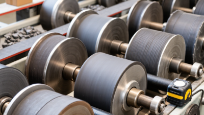
Bevel gears are designed around the direction, size, and variation of an industrial load. Their conical teeth transfer torque between intersecting shafts, often through a right angle. In a conveyor reducer, for example, the gear teeth must handle startup torque, repeated stops, and occasional shock loads. Loads rarely stay steady.
The U.S. Department of Energy’s 2014 Improving Motor and Drive System Performance sourcebook reports that motor-driven systems use about 68% of electricity consumed by U.S. manufacturing. That figure is not a gear rating, but it shows why efficient, dependable drive components matter across industrial equipment.
Designers calculate tooth-root strength and surface durability, then check whether the contact pattern remains stable under load. ISO 10300-1, -2, and -3 describe calculation methods for bevel gear load capacity, including general influences, surface durability, and tooth-root strength. Shaft deflection and housing stiffness matter too: a small alignment error can concentrate pressure near a tooth edge.
Material hardness, heat treatment, lubrication, and operating temperature also shape service life. In practice, engineers compare calculated loads with the machine’s duty cycle and leave appropriate margin for variation. Still, calculations are not the machine. A real gearbox may run hotter, dirtier, or less smoothly than the design assumptions. That deserves attention.
Bevel gears redirect rotation between intersecting shafts, often at 90 degrees. This geometry helps designers fit drives into compact gearboxes, conveyors, crushers, and machine-tool heads. Space matters. A right-angle drive can remove extra belts or shafts, reducing alignment points and simplifying guarded layouts.
Straight bevel teeth suit many moderate-speed applications.
Spiral bevel teeth engage more gradually, often supporting smoother operation under load.
Selection still depends on torque, speed, duty cycle, lubrication, and noise limits.
Efficiency also matters. The U.S. Department of Energy’s 2014 Improving Motor and Drive System Performance sourcebook estimates motor-driven systems use about 54% of U.S. manufacturing electricity. That figure covers entire motor systems, not bevel gears alone, but it shows why transmission losses deserve attention.
Properly designed and lubricated bevel stages can transfer power efficiently; poor alignment, contamination, or worn teeth can increase heat and noise. Maintenance is practical: check backlash, inspect tooth-contact patterns, and monitor oil condition. They are not maintenance-free. A bevel set may also cost more to manufacture than a simple parallel-shaft arrangement, especially when precision geometry is required. Compare layout, service access, and operating energy—not only initial gearbox cost—before specifying one.
Bevel gears serve equipment that must turn power through a right angle in a compact space. In mining, they can drive crushers, conveyor gearboxes, and mobile equipment exposed to dust and shock loads. The U.S. Geological Survey’s Mineral Commodity Summaries 2024 estimated global copper mine production at 22 million metric tons in 2023. That scale helps explain the need for dependable drives across extraction and processing plants. Bevel gears also appear in agricultural tractors, feed mixers, and irrigation drives, where shafts often meet at 90 degrees. Marine steering systems and machine tools use them too. The exact arrangement depends on torque, speed, lubrication, and available space.
Renewable-energy equipment adds another use case, though not every turbine contains bevel gears in its main drivetrain. Some designs use right-angle gearboxes in yaw systems or auxiliary drives. The International Energy Agency’s Renewables 2023 report recorded 507 GW of renewable capacity additions in 2023, nearly 50% above 2022. This growth means more equipment requiring carefully matched motion-control components. A bevel gear’s tooth contact must be checked under real operating loads, not just catalog ratings. Small alignment errors can cause noise, heat, and faster wear. That detail is easy to overlook. Gear choice is rarely tidy: field conditions, maintenance access, and duty cycles can matter as much as the machine’s headline power.
Selecting a bevel gear starts with the machine, not the catalog. Record input power, operating speed, required reduction, shaft angle, rotation direction, and daily duty cycle. Then estimate output torque, including start-up loads and sudden impacts. A right-angle drive may save floor space, but its gear geometry must match the shafts and load. Small details matter.
Check the environment, too. Dust, moisture, heat, and limited lubrication access can shorten service life. Ask for gear-rating calculations based on recognized AGMA or ISO methods, and confirm materials, tooth accuracy, mounting tolerances, and lubrication requirements. The U.S. Department of Energy’s 2014 Improving Motor and Drive System Performance sourcebook reports that motor-driven systems use about 68% of U.S. manufacturing electricity. That figure is not specific to bevel gears, but it shows why drivetrain losses deserve attention. A catalog efficiency figure alone may not predict performance in your actual duty cycle.